Awhile back I purchased a Quickie Explore electric wheelchair with the intentions of turning it into a large outdoor robot platform to continue my explorations with GPS and mounting such things as a paintball marker to it. An electric wheelchair is the next logical progression in the series of outdoor robots that I have started and never ultimately finished. I keep getting near completion of at least a basic functioning base when something better comes along. Anyways, I think and hope that along with Raven (Which I have made some more progress on, or had anyways until the rear differential stripped out on the savage flux RC car base) this will be the final outdoor robot for a while. I have always dreamed of having an electric wheelchair with which to hack into an outdoor base because they are close to an ideal large outdoor base. Lots of battery life and payload capacity, like LOTS, very good motor controls built in, and very stable. I consider this and Raven to be parallel developments, as while they are both outdoor bots, they have quite different properties, raven being reletively small and very very quick and this one being much larger, slower and longer lasting. Perhaps in the future when I become a better programmer I will be able to make use of Raven's speed, but for now slow and stable are very good traits to have in an outdoor robot. Anyways, I had anticipated using the stock motor controller and joystick assembly, but taking the actual joystick out and emulating it with an arduino and some additional electronics. Before I opened it up, I thought that the joystick would use a couple of potentiometers as most joysticks do, and which I would be able to replace with a couple of Digital Potentiometers that sparkfun sells.
Well when I opened it up that was not the case at all. There was a large circuit board holding a bunch of electronics and an 8 wire ribbon cable attaching to a very scary looking joystick. After doing a bunch of research on the net, I found out that in fact it is a sealed unit that contains not 2 but 4 hall effect sensors which it uses as outputs. Each direction (X and Y) have two hall effect sensors that output similar but not identical signals as a sort of failsafe. The controller looks for the signals to be slightly different within a tollerance but mostly the same and if either signal strays too much from its partner, the controller detects this change and locks out. So in order to emulate the joystick's outputs I need true analogue voltage fed into the control board. I am not sure yet, time and some testing will tell, but I may be able to feed the same voltage into both of the pins that the board expects to see slightly varrying signals from the two hall effect sensors and recalibrate the control board to think that is normal. If I can then I can get away with only needing two analogue signals instead of the 4 the joystick currently feeds the board. Time shall tell.
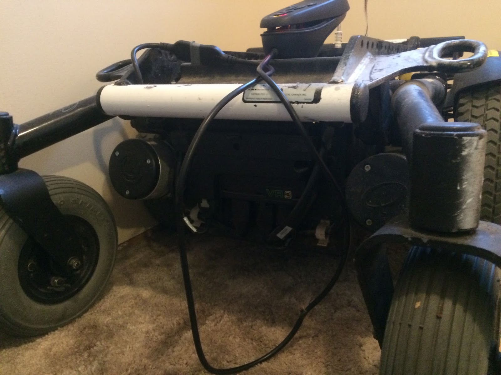
Enough of the boring postulating and onto the pictures of what I have got going right now!
Last night I was able to work some on the practical hacking of the joystick assembly.


I downloaded Adafruit's mcp4725 library and uploaded the triangle wave demo sketch to the arduino, connected up a mcp4725 and.... Nothing. I had changed the I2C address to 0x60 in the example because the amazon clones of the breakout boards were clones of the sparkfun boards so I foolishly thought that they would have the same addresses as the sparkfun ones. A friend of mine with more paitence than me read a bit of the datasheet and rewrote the program to initialize 6 mcp4725 on all six (apparently the maker of the chip actually allows 6 addresses depending on the version, tho only 4 are commonly availible. Sparkfun's and Adafruit's) availible addresses and give a constant voltage instead of a triangle wave, and this time we had some action! Turns out the clones I have have the adafruit addresses of 0x62 and 0x63!

#include <Wire.h>
#include <Adafruit_MCP4725.h>
Adafruit_MCP4725 dac62;
Adafruit_MCP4725 dac63;
void setup(void)
{
dac62.begin(0x62);
dac63.begin(0x63);
}
void loop(void)
{
dac62.setVoltage(4095, false);
dac63.setVoltage(1024, false);
}
Thats about as simple as it gets. The values are based on a formula you can find in the datasheet, but pretty well 4095 is 100% of the supply voltage and 1024 is about 25%. In this case it spat out 4.96v and 1.24v. Pretty freaking decent. Unfortunately I don't have any pictures or video of that part happening, but it all worked out perfectly. Thats as far as that part has gotten, it will probably stay in about that state on the breadboard until some more testing with the wheelchair is complete.
Speaking of wheelchair testing, before I got too carried away, I wanted to make sure all my solder connections were all good and some extra length of wire between the joystick and controller was going to be OK so I got everything all together and hooked up on the wheelchair and tried it all out.


Annnnnnddddd heres the video of the quick test I did to make sure everything is still running tip top.
Thank you for sharing your work. I recently came across a Jazzy Sport 2, but I don't have the joystick controller. Any advice on hacking (with Arduino) the 4-prong adapter connected to the motor controller? Is there anyway around having to purchase (and hack) the joystick?
ReplyDeleteHi Skyler!
DeleteFrom the research that I have done, I understand that most wheelchair makers use some sort of proprietary closed interface to connect from the joystick controller to the motor controller box. My strengths certainly do not lie in programming or reverse engineering protocols, that stuff is far over my head. I chose the solution above because it played well into my relative strength in electronics. So I am sorry but I cannot offer you any advice about sniffing out the jazzy protocols. Best of luck on your project, make sure the first few times you hook power up the drive wheels are off the ground. Little robots bump into the wall. Big ones tend to make holes :P
Hello it is a very good work.Do you have the datasheet of the joystick?
ReplyDeletei am currently also confused with the joystick