Monday 31 March 2014

More Window

Just a little work done, but besides the electronics/battery box in the middle that I have yet to mount, this will probably be all the progress I make untill my KK2.1.5 board comes in the mail. Starting to look like an Octocopter...

Sunday 30 March 2014

PKP (trials and tribulations of building a homebuilt motor controller, Pt. 2)

When I last posted about PK's motor controller, I had just let the magic smoke out of a MOSFET from a cheap cordless power drill, and ordered 8 of these 60V 30A MOSFETs from sparkfun. Well, a little while later I had a pretty little red box show up, and it was time to get started:
 Also on hand for this project, I had the heatsink from an old computer (already cut in half in this picture)
And the ever faithful relay part of my motor controller
I set to work on the heatsink, planning on drilling and taping 6 holes into it, and cutting it in half so each channel would have three MOSFETs wired in parallel. Well, the heatsink had other plans, and I ended up snapping not one, but two drillbits in seperate holes on the heatsink. At this point I decided that rather than try my luck with the other half of the heatsink and probably end up with the same fate, I would cut off the portions of each heatsink that were ruined, tap the holes, and hope that two MOSFETs in parallel would be enough. Here is a picture of the heatsinks that I ended up with:
I then soldered up a board with 4 MOSFETs plus all of the necessary connecting wires:
And put it all together:
Copious quantities of heat sink compound was used, and I put a cut up chunk of circuit board between the heatsinks to prevent them from shorting out on one another (MOSFETs are different than voltage regulators and the like in that the tab on them is not connected to ground, it is connected to the output, so it is important to isolate the channels from each other) The whole assembly is held together by a couple of zip ties (I love my zip ties :) )
I taped an unused computer fan to the top of the assembly, connected it to the relay block and...
Found out that the MOSFET driver board that I made for the last batch of MOSFETs was dead. So this is the second driver board I have built and then fried, and I am getting a little iritated, but I am this far in already, so I gotta keep going, so I broke out the multimeters, battery and electronics, and prototyped another one,
cut the disfunctional one off of the relay block driver,
and soldered up yet another board:
I (kinda, maybe) learned some lessons from the other two that I fried, and made this one completly removable using 0.1" male and female headers so that if it fries, I can swap in a new one without cutting any wires. I also doubled up on the transistors for each channel, hopefully giving a little bit of redundancy and added a header for the computer fan. I stuck it back on the motor controller and now have a fully functioning motor controller:
The male spade connector is for ground, power is supplied to one of the four relay terminals in the centre of the brick, the heat shrink tub covered two pin connector is both ground pins to be connected to the logic circuit, the four pins are for direction control, and the two left are speed control.
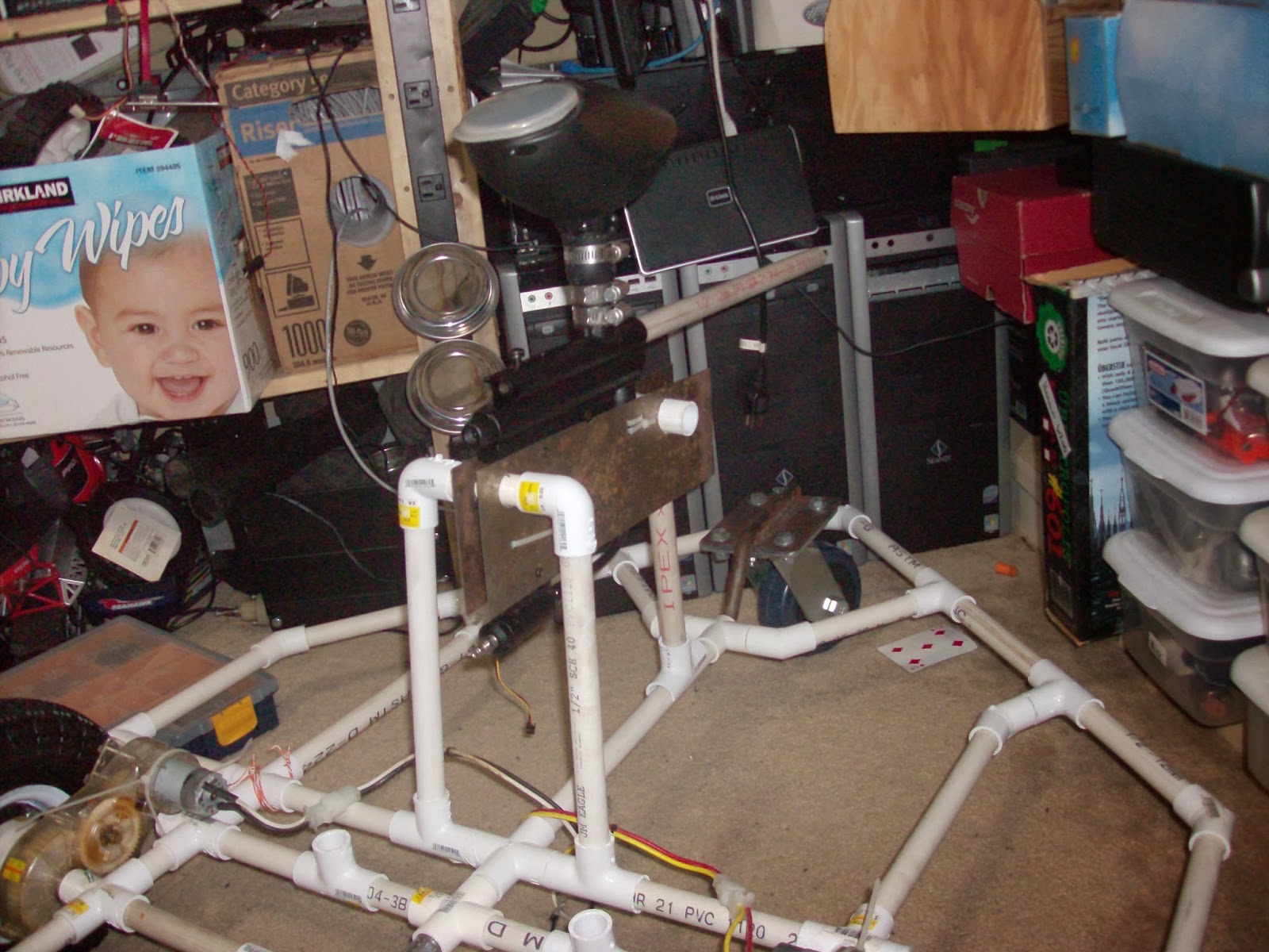
Here is a picture of it mounted on PK:
 The interesting thing about large robots such as PK is that, in contrast to smaller ones, it is not as important where things such as a motor controller or MCU is mounted, and it might change around a lot, so that is probably just a temporary resting place. That said, here are a couple more views of how PK is right now:
Due to not having a lot of time and the fact that my front yard is one big mud puddle while my back yard is still under a bunch of snow, I have not yet tried the motor controller on PK's motors yet, I just hope that the two MOSFETs per channel will stand up to the motors, cause if I let the magic smoke out of these, I might not have the motivation to rebuild the speed control part AGAIN, and I am a little on the broke side to buy a commercial speed controller. The paintball gun isn't quite operational yet, I still need to buy a right angle fitting for the remote line so that it will fit between the end of the gun and the main battery. That's all for now, I hope to try that motor controller out soon.

The Window progresses (just a little)

I will start this off with a picture of the quadcopter that I bought, plus the 4 arms from my disasembled quad, both of which were then totally disasembled to be used in The Window:
I took those completly apart, and was left with this motley collection of 8 motor, ESC, and propeller combos:
The top (or in the second picture, right) four are from my friend's quad, and they have had their power wires extended, I think this might actually be handy for mounting the ESCs, and they all have 3.5mm male bullet connectors on the power leads. I plan to make a nice wiring harness using 12 gauge wire that will have 4 XT60 connectors for power (I only plan on using two batteries at a time, but its nice to have the capibility to use 4 if I would like), and wires running up the arms for power to each of the two ESCs on that arm. I wanted to have nice red and black wiring, but cheapness reared it's ugly head, and I ended up only getting 10 feet of white instead:
                                                 
I also mounted the motor mounts to the mounting tees, and gave the motors a test fit. The blades seem to have a good amount of clearence between one another, and the spacing seems quite good too, gotta love trigonometry.
 Here is a closeup of the motor mount:
The zip ties hold it in place quite securely. In this picture I have yet to clip the excess from the tie, but that shall happen. Three ties hold each motor in place.

That's all the progress to date, stay tuned for more at some point.

Saturday 29 March 2014

The Window (beginnings)

Awhile back I made a simple and cheap quadcopter using parts mainly from Hobbyking and the local hardware store, you can read the letsmakerobots writeup I did on it here. A friend of mine also built a similer one using mostly the same parts (we placed one big order with twice the parts needed to make a quad). Fast forward a year or so, and my quadcopter is sitting in parts in a box on my shelf, victim of an upgrade that never quite got finished, and my friend's is also sitting unused on a top shelf. Seeing as the quads were both built with identical electronic parts, and his was also unused, I decided to see if I could buy his off of him, and put the two together to make a octocopter. He conceded, and I was now the proud owner of two disfunctonal quadcopters, plus some extra parts. Step one was to find a suitable octocopter control board that was in my price range and simple enough for me to be able to use. I looked around, and found Hobbyking's KK2.1.5, but more on that in another post. Step 2 was to build a frame, after the sucess I have had with a PVC frame, and the miserable failure I had with a storebought frame, there really wasn't any decision to make. Perhaps later in the future when I become a better multirotor pilot, less prone to crashing, I will invest in a different frame, but for now its 1/2" PVC for me :)

I spent a while with some graph paper, a ruler, and a pencil determining the best frame setup that I could come up with that used only standard pipe fittings,
 
and after I had sketched a bit I decided on this setup:
 
With two motors connected to each arm that radiated out of a + fitting, much like my previous quad. A little bit of trigonometry later and I had the legnths of pipe that I would need in order to space everything in a nice octaganal shape, and I also decided to stregnthen the frame a little by connecting the corners to each other, just like this:
I measured and cut all 20 pipe segments, and then faced them and got their legnths perfect on a lathe. 4x 11.85" legnths, 8x 6.5" legnths and 8x 4.25" legnths:
Next up was drilling three holes in the top of each of the 8 motor mount tees for use in fastening down the motors. I found that a very good way to fasten the motors to the frame was by drilling holes in the tee, and affixing the motor to the tee using zip ties. This is a simple, light, easy to repair, and cheap setup, and most importantly, it has a little "give" in it, so if I make an especially hard landing, the zip ties break instead of the motors. I have had that happen several times, and it is much nicer than replacing a motor (my friend decided to screw his motors down, and broke two or three of them in hard landings, I have yet to break one.) This is a picture of my quadcopter's motor mounts, my octocopter will use exactly the same method, except with only 3 zip ties per motor.
Here is all of the pipe and fittings used to make the frame:


And a couple of pictures of the completed frame, it is approximately 3' on diagonal.


 Everywhere that a pipe goes into a pipe fitting, I match drilled a hole and drove a small wood screw into the join to ensure that none of the pipes will pull out or rotate. The frame is very sturdy and has almost no flex. It also happens to look very much like a windowpane, which is where it gets it's name, The Window.
Price: $13
Weight: 1.1 kg
Durability: Dang this thing is durable, it would take a lot to break it, and if it does, parts are cheap and avalible at the local hardware store.
Looks: So apparently some people find this to be important. I have never understood humans. In other words, Dat Pipe :)

Well, that's all for now, updates will come sometime.

Another really short PKP

I took PK into the shop today and finished up his frame joint where the axle and long spar meet. It has had holes drilled where they meet in order to lock the spar from rotating, but I never got around to putting properly sized bolts into them which caused some slop in the connection. So I drilled the holes out slightly more, tapped them with a standard 1/4" NC tap, and threaded some bolts in from the bottom: (These pictures are with PK upside down)


The bolts stuck out a little on the top of the frame, and they are right where the main battery sits, so I didn't want any high spots, so I ground down both of the bolts, and while I was at it, the high points on the metal T too, so the battery sits evenly on all of the contact area.
 
The threading of the holes means that I don't need a nut on the other end of the pipe to keep it in place, so this configuration works well. Anyway, that's all the progress for now, told you it would be short ;)

Thursday 6 March 2014

PKP

I finished up the paintball gun mount/trigger plates that I mentioned in a previous post, they are just scrap sheet metal with a number of holes drilled in them:

The top one also has a cutout for the trigger servo to go thru. I mounted the servo to the plate, screwed the plate to the grip holes in the gun, and gave it a try:
Here is a video of the servo triggering the paintball gun to fire, this time I had a full tank of air, so it auto-recocked like it should. Again, the red robot and Tx were the fastest and easiest thing I had to try out the servo.
And a couple pics with the other plate on, and everything together:

 Closeup of the servo mounting plate:
 As you can see, I ended up using two zip ties on the front instead of a hose clamp, and I further reinforced the plates on the back by wraping another zip tie around the handle.

And finally, a couple of pics of the gun "mounted" on PK. In reality the gun will be closer to the base of the bot, and the front part of the tripod will be hose clamped down.


I also have been working on the motor controller, but its not done, so I will save that update for another post.