Thursday, 26 December 2013

PKP

I made a little more progress on Project Killzone, I wired up everything again for a test, and put a different tx/rx pair for a little better control:
And I took it outside for another test (these videos probably should have been edited into one continous one, but the computer I'm on right now doesn't have any video editing software)
I also took advantage of our vacant car port to give me a slightly larger test space:
Both of those videos were ended because my newly aquired action camera fell off of its just-crammed-under-a-pipe-fitting mount, and on the second one, it was actually recording, here is the footage:
And, one last one (a little longer, poor videography skills displayed, and not fully functional due to a wire pulling out, I think, but there nonetheless)

Of course, Murphy's law was in full effect during the filming, I would turn the camera on, film for a bit, a wire would get dislodged, and it would start acting funkey. stop filming, fix the wire, and it worked fine until turned the camera back on. I did have it working a little longer than the footage shows, but, of course, no footage of it :)

Well, Project Killzone is my largest project to date, and with a big bot like this, I have learned some new things, chiefly, you can't just slap an arduino and some assorted electronics on the back of something this size, plug the wires into those headers, and expect them not to pull out and ruin your filming. So next time I take this guy outside for some testing, I will have some proper (well, proper-ish) strain reliefs on all the wires, and probably a nice electronics box too. Next steps will be mounting the paintball gun+servo for the trigger (I got a nice remote line for Christmas, so I will be able to have my paintball gun tank mounted somewhere besides the very end of the gun) and getting the speed control functioning on the motor controllers. My leftover motor controller from GPS was having some problems, so I cut off the speed control section and just left the relay portion untouched. I will be re-adding the speed control part after I figure out if my MOSFETs are still good, and get around to building a driver circut for them. Speaking of which, I am contemplating making a picaxe driver board to turn my dumb motor controller into a smart one, just make it accept 2 R/C signals and take care of all the messy relay and MOSFET driving. But that is a topic for another post.
PK as he stis now:


Monday, 16 December 2013

PKP (It's ALLLLIIIVVVVEEE!!)

I should be doing schoolwork right now, so this will just be a quick post, I got some more work done on PK, here are some pictures: First I finished up the spacers on the rear (I have decided that the castor will be the front, at least for now.) axle:


 And I added some quick motor supports, tie-down-strapped the battery on, wired up my motor controler and RC reciever to my arduino and wrote a quick test program.

Shortly after, I took it outside to test, first on the deck, and then out in my yard (which is pretty snowy) sorry for the poor lighting, it was dark, and these were taken on an old camera.
Well, it worked. Not well in the snow, and I deffenatly need a better control sceme, but it still moved :) The next step was to build a frame, so off to the hardware store for a few pipe fittings and 20 odd feet of pipe and in a couple hours I had a mostly done frame:


I havn't gotten any further so far, and now it sits in the corner of my bedroom taking up a sizable chunk of floor space (at the moment 39 inches long and 37 inches wide) and with the battery weighs about 45 pounds. (I have taken the battery out for storage, as it causes the rear axle to sag a little, and I don't need to stress it needlessly)

(Music) I like big bots and I cannot lie......

Wednesday, 11 December 2013

PKP (Project Killzone Progress)

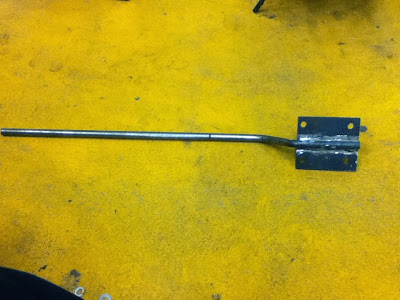
Last night I welded the aforementioned plate onto the aforementioned steel rod, creating my castor mount, and the last critical piece of PK that I did not have. All that needs to be done now in order to get a drivable (tho not finished) platform is to mount the castor assembly to the main axle, put the PVC spacers on the main axle, mount the battery and motor controler, and wire it up with some rudimentary brains. Once that is done, I can get onto testing the basic platform, which might be interesting actually, I live up a mountain in Canada, and its a tad snowy here :) Anyway, some pictures, castor mount first:


Not the best welding job, but not the worst either, it has not bad penetration, and this part shouldn't be under huge amounts of stress, so it should work fine.

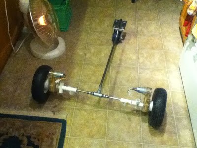
And I took a couple of pictures with the castor assembly quickly mounted to the main axle, note that when it is actually mounted, it will be shorter, I just cut it at that length to give me room to work.
Looking at that right now makes me think of the battlebot weapon style, the "Thwackbot" 
Couple of close ups of the castor mounted:

And finally, one close up of the tee. The tee is 1/2 inch, and the bushings and nipples on the main axle are 3/8, that size chosen because the ID of the nipples fits the main axle's OD almost perfectly. As mentioned previously, the 1/2" nipple was reamed out to let the castor assembly's rod to fit into it nicely. When completed, the 1/2" nipple and rod will be match drilled and bolted together to prevent rotation, and the nipple itself will be tightened into the tee, match drilled and bolted, also to prevent rotation.


Tuesday, 10 December 2013

Progress on Project Killzone

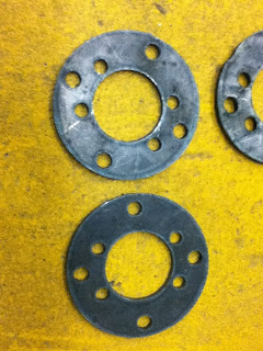
I have decided to call my large outdoor robot using the power wheels motors Project Killzone, because it will be my first weaponized robot (first with a paintball gun, and perhaps later with a small potato cannon). A couple of weeks back, I purchased some 10" I think pneumatic wheels and tires, with bearings set into them, as well as a 5" castor for the back (or possibly front, I still have not decided if I am going to make it a taildragger, or have a nose wheel) with the intention of fabricating an adapter plate that would bolt onto the 4 bolts holding the hub of the wheel together, and have the 6 (later changed to just 4, due to spacing issues) bolts sticking up to fit into the depressions of the drive motors. I have acecss to a CNC plasma cutter, so I decided to use it to fab the adapter plate. I designed the plate, and after a few false starts (see the pictures) I had 2 nice adapter plates:


The wheels also have a slightly larger ID than the power wheels axle, so some bushings were made to correct that. Here is a pic of all the things that were fabbed this weekend:

These are some photos of an adapter plate bolted onto the wheel:


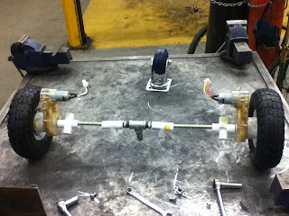
And here is the whole bot as it sits, the metal tee in the middle of the axle is where the tail (or nose) wheel assembly is going to go, the tee is 1/2", as is the pipe nipple. The pipe nipple has been reamed out to a nice ID, where a metal rod fits in nicely, the metal rod goes out, and has a dogleg bent into it, in order to make the end where the castor will mount (the castor's mounting plate is a little higher than the main axle) higher. I shall weld the end of the rod that the castor is to be mounted to to a metal plate with the same dimentions as the mounting plate on the castor, and holes drilled into it for the castor to mount on. The PVC fittings are for the rest of the frame, the +s to make the outer frame and the tees will go straight up for mounting a paintball gun, compass sensor, GPS antenna, etc. on. I still plan to use the stainless dishwasher cover as a baseplate to bolt on after the frame is made.