Showing posts with label motor controller. Show all posts

Thursday, 11 December 2014

Yeah I can't stick to one project.

I have project commitment issues. But hey, whatever, they all need to get done someday! Anyway, with my Camaro sitting outside just waiting and calling to me, I had to caniblize it. Brought it inside and started taking stuff off. I also brought PK, or what was left of him after moving, upstairs and ripped the parts off him too. Ended up with this collection:
The motors are a little different, or rather the gearboxes are. The new ones have different mounting flanges, and the pass thru shaft hole size is slightly smaller in the new ones. But the gearing looks identical and the motors themselves also do. And big bonus, the crazy wavy hexagon that power wheels toys use to transfer power is identical on both, so I can use all four wheels from the Camaro. Also, the snazzy mags just pop out leaving me with some plainer, but honestly more my style wheels. As snazzy as those are, I think I am going to be leaving them behind when I go forward. Ill keep them around and if I ever need to enter a paintball packing autonomus car into a car show or something, I can add them for the extra bling. In addition to being slightly larger diamiter, the other car's axle was also longer than this one. but that is no problem, I shall just cut it down and tap some nice threads on the end like the original car had. Here is a super quick mock up I did to get a generall idea of size:
You can clearly see the legnth difference between the two in this pic tho the angle of the camera does cancel some of it out.

But thats not everything to do with PK yet! I never made a post about this but a few months back I visited princess auto in Kelowna and found these beauties really cheap in the surplus section:
The are HUGE open contact DPDT relays. As I said, got them very cheap, but unfortunately they have a 24v coil. I anticipated being able to drive them at 12v no problem, but I just tried them on a 12v battery and no dice. No problem, I will just make a voltage doubler. It will make things slightly more complicated but not overmuch.

Rebeginning.

Tuesday, 8 April 2014

PKP (it's alive again)

In my last post about PK, I had completed the motor controller, but had not yet tested it, so I started off by getting out my UNO and writing some test control code for the motor controller:
I got the code all written up, and gave it a test with two multimeters hooked up to the outputs (Unfortunately this video is really dark, it looked lighter when I was taking it)
And hooked it all up and gave it a try (The motor directions are reversed in this video, I fixed that shortly after)
The code running on the UNO during all of these videos is as follows:

#define in1 3
#define pwm1 9
#define f1 5
#define b1 7
#define in2 4
#define pwm2 10
#define f2 6
#define b2 8
void setup()
{
  // Channel 1:
  pinMode(in1,INPUT);
  pinMode(pwm1,OUTPUT);
  pinMode(f1,OUTPUT);
  pinMode(b1,OUTPUT);
  // Channel 2:
  pinMode(in2,INPUT);
  pinMode(pwm2,OUTPUT);
  pinMode(f2,OUTPUT);
  pinMode(b2,OUTPUT);
  Serial.begin(9600);
}

void loop()
{
 int p1=pulseIn(in1,HIGH);
 int p2=pulseIn(in2,HIGH);
 int p3=p1+p2-1500;
 int p4=p1-p2+1500;
 p1 = constrain(p3, 1200, 1800);
 p2 = constrain(p4, 1200, 1800);
//============= Channel 1 =============
 if(p1 > 1530)
 {
   int s1=map(p1, 1530, 1800, 255, 0);
   analogWrite(pwm1,s1);
   digitalWrite(b1,LOW);
   digitalWrite(f1,HIGH);
 }
 else if(p1 < 1470)
 {
  int s1=map(p1, 1470, 1200, 255, 0);
  analogWrite(pwm1,s1);
  digitalWrite(f1,LOW);
  digitalWrite(b1,HIGH);
 }
 else
 {
  analogWrite(pwm1,255);
  digitalWrite(b1,LOW);
  digitalWrite(f1,LOW);
 }
//============ Channel 2 ==============
 if(p2 > 1530)
 {
   int s2=map(p2, 1530, 1800, 255, 0);
   analogWrite(pwm2,s2);
   digitalWrite(b2,LOW);
   digitalWrite(f2,HIGH);
 }
 else if(p2 < 1470)
 {
  int s2=map(p2, 1470, 1200, 255, 0);
  analogWrite(pwm2,s2);
  digitalWrite(f2,LOW);
  digitalWrite(b2,HIGH);
 }
 else
 {
  analogWrite(pwm2,255);
  digitalWrite(b2,LOW);
  digitalWrite(f2,LOW);
 }
//====================================
delay(15);
}

For my actual outdoor run, in order to get some footage, I made up a quick little camera bracket for my transmitter, I call it the "forever alone camera mount"


And I also made a little mount for my action cam to mount on PK in place of the paintball gun, since I do not yet have the necessary parts to make it opperational yet.
And with all that set up and working, I went out and drove it around my driveway for a bit (woohoo, my first legitimate run :)) The first video is me filming, and the second is from PK's camera
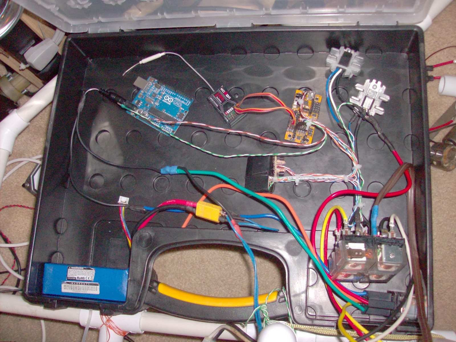
Well, it works. After I finished driving it around, I stuck it in an outdoor shead, here are a couple op pics of the various parts, and the whole thing as it sits:
Motor controller:
 Arduino:
 The whole backside:
 And from the front,
 Top,
 And side:
Anyway, it runs, which brings a smile to my face :) Onward and upward!!

Sunday, 30 March 2014

PKP (trials and tribulations of building a homebuilt motor controller, Pt. 2)

When I last posted about PK's motor controller, I had just let the magic smoke out of a MOSFET from a cheap cordless power drill, and ordered 8 of these 60V 30A MOSFETs from sparkfun. Well, a little while later I had a pretty little red box show up, and it was time to get started:
 Also on hand for this project, I had the heatsink from an old computer (already cut in half in this picture)
And the ever faithful relay part of my motor controller
I set to work on the heatsink, planning on drilling and taping 6 holes into it, and cutting it in half so each channel would have three MOSFETs wired in parallel. Well, the heatsink had other plans, and I ended up snapping not one, but two drillbits in seperate holes on the heatsink. At this point I decided that rather than try my luck with the other half of the heatsink and probably end up with the same fate, I would cut off the portions of each heatsink that were ruined, tap the holes, and hope that two MOSFETs in parallel would be enough. Here is a picture of the heatsinks that I ended up with:
I then soldered up a board with 4 MOSFETs plus all of the necessary connecting wires:
And put it all together:
Copious quantities of heat sink compound was used, and I put a cut up chunk of circuit board between the heatsinks to prevent them from shorting out on one another (MOSFETs are different than voltage regulators and the like in that the tab on them is not connected to ground, it is connected to the output, so it is important to isolate the channels from each other) The whole assembly is held together by a couple of zip ties (I love my zip ties :) )
I taped an unused computer fan to the top of the assembly, connected it to the relay block and...
Found out that the MOSFET driver board that I made for the last batch of MOSFETs was dead. So this is the second driver board I have built and then fried, and I am getting a little iritated, but I am this far in already, so I gotta keep going, so I broke out the multimeters, battery and electronics, and prototyped another one,
cut the disfunctional one off of the relay block driver,
and soldered up yet another board:
I (kinda, maybe) learned some lessons from the other two that I fried, and made this one completly removable using 0.1" male and female headers so that if it fries, I can swap in a new one without cutting any wires. I also doubled up on the transistors for each channel, hopefully giving a little bit of redundancy and added a header for the computer fan. I stuck it back on the motor controller and now have a fully functioning motor controller:
The male spade connector is for ground, power is supplied to one of the four relay terminals in the centre of the brick, the heat shrink tub covered two pin connector is both ground pins to be connected to the logic circuit, the four pins are for direction control, and the two left are speed control.
Here is a picture of it mounted on PK:
 The interesting thing about large robots such as PK is that, in contrast to smaller ones, it is not as important where things such as a motor controller or MCU is mounted, and it might change around a lot, so that is probably just a temporary resting place. That said, here are a couple more views of how PK is right now:
Due to not having a lot of time and the fact that my front yard is one big mud puddle while my back yard is still under a bunch of snow, I have not yet tried the motor controller on PK's motors yet, I just hope that the two MOSFETs per channel will stand up to the motors, cause if I let the magic smoke out of these, I might not have the motivation to rebuild the speed control part AGAIN, and I am a little on the broke side to buy a commercial speed controller. The paintball gun isn't quite operational yet, I still need to buy a right angle fitting for the remote line so that it will fit between the end of the gun and the main battery. That's all for now, I hope to try that motor controller out soon.

Thursday, 2 January 2014

PKP (Or Trials and Tribulations on Building a Homemade Motor Controller)

I decided I had done enough mechanical work on Project Killzone for the moment, and should give the electronic side some love too, so I started working on my motor controller. The motor controller I am using was built for another (failed) outdoor bot named GPS Here is the link to his project page on LMR, for those interested. You can find a couple more details and pictures on the build process on by following that link. As I mentioned in my earlier posts, I couldn't get the speed control to work on one of the channels when I tried using it PK originally, so I just cut out the speed control part of the circuit, and used only the direction control portion to drive the motors for testing. So, to start, I had one relay block, a driver for the relay block, and the goal of a motor controller that has variable speed and direction control inputs that respond to servo signals (1-2 ms, with 1.5 being centre or stop).

Here is a schematic of the relay+driver portion of the controller: (drawn by hand and scanned, forgive the quality)

And here is a schematic of the speed control portion: (this one was found on the Internet)


This circuit sits where it says "speed control circuit" on the first schematic, except the top leg of the MOSFET connects directly to the wires going to the relay, instead of going thru the "motor" connector and to 12v. Also note that when I built this, I used 2N3904 transistors for the relay section, some random NPN transistors that were sitting in my parts bin for the MOSFET drivers (ran out of 2N3904s) and some generic N-channel MOSFETS that came out of 18v cordless drills. Here is a link to the relays I purchased from ebay (5 relays for $13 shipped) (If that link is down, just type 60a 12v relay into ebay, and scroll down)

I already had the relay drivers set up and working nicely, so the next step was to figure out if my MOSFETs were fried, some quick circuit building and I had this:
I found out that 2 of the 4 MOSFETs I had from the drills were fried. Unfortunately, they were different types (2 different brands of drill) one heftier than the other one. I didn't have much of a choice, so I pressed on. I mentioned that in another post that I would try making this into a smart controller with the addition of a picaxe to receive signals from the master, and do the dirty work of driving the MOSFETs and relays. Well, I tried, but picaxes, while great chips, were not designed with math in mind, and my programming skills are not up to figuring out how to do what I wanted with the picaxe's limited math ability. So I switched to an Arduino, in this case, a Dagu Micro Magician. The Micro Magician is waaaayyyy overkill for this application, and I am basically wasting it, but right now I only have 2 Arduinos, and I didn't want to give up my UNO for this.

Some pictures taken while I was prototyping:
 Close up of the Micro Magician (the RC rx was just used as a handy source of servo output signals):
 Close up of the breadboard-ed MOSFET driver circuit:
When one is prototyping, one's workspace tends to get a little messy:

Once I had determined I had two good MOSFETs, and everything was working well, I moved the breadboard circuit onto some protoboard:
And wired up the entire thing:
Well, if that isn't the strangest shaped motor controller you have ever seen, I'd like to see a stranger one :)

Here are some close ups of each subsystem in the controller, first of the relay block:
The brown wire at the top is + power, and the 4 free spade terminals are the two motor connections.

MOSFETs:
Notice how they are different? I bolted the lower-amp one to the heat sink of the dead higher amp one because it was a lot higher quality.

Buffer boards:
The tape covered one is for the relays (also has the old MOSFET driver circuit, but I just cut the wires and left it alone, the relay driver part still works great) and I just zip-tied the new MOSFET driver board beside it.

And finally, the brains:
Such a waste to use such a powerful board for such a menial task. Due to the characteristics of the Micro Magician, the motor driver accepts 3.6-9v over the power wires, and I also soldered some in-line 4.7K resistors on the input wires, so it will accept 5v control signals (the Micro Magician is a 3.3v device)

Here is a video edited together from footage taken while prototyping, first connected to LEDs instead of the relays, and using lamps as loads on the MOSFETs, then with the LEDs replaced by the relays, and finally all soldered together with multimeters instead of motors. (Note that the voltage is higher when the stick is going one way than the other in the movie, this is due to the signals generated by the transmitter not being equal in both directions)
So once the motor controller was done, I slapped it onto PK (who also got a more improved brain bucket that will stay until I mount the paintball gun (It will get in the way of the mount, and hopefully by then I will figure out a seperate container for the motor controller)) and added my UNO, an rx, a LIPO for logic power, and a custom power distrubution harness complete with relay for switching power to the motor driver and a switch for the UNO, wired it up, and tried it out.
(note that I don't have the UNO wired to the motor controller or rx in this picture, and the rx you see was removed and replaced by a different one.)

A front view picture:
 And back in it's corner:
Here is a video of everything wired, and being controled by a transmitter:
Unfortunately, as that video was being taken, the magic smoke was being let out of the MOSFET from the less powerful drill, so I don't have a video of it driving with the variable speed controller hooked up, because I haven't actually driven it. Anyway, I have bought some (8) 30 amp N-channel MOSFETs from sparkfun.com (Here is the link to the MOSFETS I will be using) and when they come, I will be using at least 2 of those in parallel for each channel, and probably screwing them to an old computer heatsink with a fan mounted over it.

Ahhh, the fun of building your own motor controller for big motors :) That's all for now folks.