Showing posts with label The Window. Show all posts

Tuesday, 9 December 2014

Goodies :)

Over the weekend (yes I am a little late, but life is busy) of the sixth and seventh, I was down in Spokane and I went to the wonderful sketchy terrible store that I love to find great deals at so much. Jeez I love that store. They actually took the piles of junk that are my favourite part out of the normal stores and moved them to one store exclusively full of total junk, and its like paradise in there. Anyway, so I bought a couple things, from least to most impressive here they are:

Two more night vision security cameras, cause I just can't get enough of those :) 
No particular plans for these two little suckers, just put them in stock for next time I need a security camera. Perhaps if I ever find the need I will set them up with a computer and a video capture card and a huge hard drive for some monitoring of my place. 

Two of these LED lightstrips. They are 5 meters long with 27 segments of 6 LEDs each.
They came with the little box you can see in the top right hand corner, its designed to recieve a signal from an IR remote control to control the pattern, but neither of them came with the remote. Anyway, I googled around for a while and found that I could simply control them with my arduino using Adafruit's awesome NeoPixel library.
There is my ugly hacked together setup to see if it actually worked. Which it did :) here is a video of both of them running, the one in the spool is the stock demo mode that it defualts to when its on, and the unrolled one is the one being run by the arduino.
The only thing to note is that on the spooled one, there appears to be a connection break about half way thru, but if you flex it a certain way, it still works as is evident in the video. Because of the way you can chain these things its no big deal, Ill just cut that one segment out and resolder them back together, or use them as smaller strips. I plan on adding these to The Window for a nice light show as well as orientation, as suggested by Duane Degn on The Window's Letsmakerobots page.

And lastly I picked myself up a Chevy Camaro...


 Ok not really:
 A couple of posts back I mentioned I have trouble sticking with one project, and its true. I really do. Anyway, I picked this bad boy up to help totally revamp Project Killzone. Pretty much ever since I picked up the two motors that are in PK now I have wished to have two more so that I could make a nice sturdy 4 wheel drive chassis instead of the 2 wheel drive one I have now. Anyway, the oppertuinity came along finally to get two more at a resonable price and also, I think (think, have not tested this yet) I can use all four wheels that came with the car, cause they don't appear to need the adapter couplings that the other wheels needed.

As you can see, it uses identical wheels on the front and back, excellent for me :) and if the motors are the same then I should be able to just slip the new wheels onto the old motors. If that works, PK will end up looking signifigantly different.

The best part of this all? All of the above was purchased for a grand total of 25 US dollars. Not too freaking shabby considering that is the price for ONE meter of LED strip from sparkfun.com and if you want 5 meters? $120. Granted, they have more LEDs and each individual one is addresable, not every 6, but still. Quite the deal I'd say.

Well thats really all for now, once I get something done on my projects, ill post the proof :) Happy Hacking!

Monday, 8 December 2014

A sorely overdue update on The Window

So after I posted about my future plans of mounting a paintball gun to The Window, and making a refrence to the pan/tilt turret I had mounted on it, I realized that I never actually got around to posting that update. All of this was done way back near April sometime, but I never did anything with the pictures. Anyway, to the good stuff.

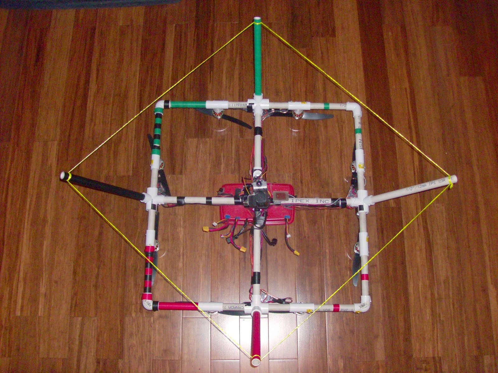
Before I get into the nitty gritties, here are a few shots of the whole thing from different angles:
As you can see, I added some landing gear to get it up off the ground in order to mount the gimbal below. The landing gear is made from some more 1/2" PVC and 4 1/2" to 3/4" tees that had half of the the T part cut away so they could be screwed to the edges. It was straightforward with two things to note, the dimond shape is due to sloppy work on my part not getting the landing gear tees all mounted at the same angle and thus needing different legnths of pipe to make it sit on all four legs, and the string running around the landing gear is due to the frame flexing a little without the support. When there was no string running around the perimiter, due to the angle, the legs would flex out, causing the 4 center arms to flex and be under stress when it was sitting on the ground and potentially breaking them on a hard landing. My solution was to run a string around all of the legs and so keep them from being able to bend outwards. The string itself is one strand from a DCCB 1800 YG Dacron rope used to Aero tow gliders. There was some short ends left over from making glider tow ropes and I snagged some, one strand from the rope is more than strong enough and has absolutely no stretch at all making it perfect for this.

Using my usual ultra high quality manufacturing methods of zip ties, hot glue, and this time a little aluminum, I cobbled this sucker together:
I originally thought that my ATC mini would output video as it recorded, but it turned out that the video out jack was just to be used for watching the footage afterwards, useless for what I wanted. So after struggling around for a little while and burning out at least one board-level camera I ended up with the ugly-as-all-get-out (whats new eh? It fits with the rest of the build) camera/solder/hot glue job you see there. I think the camera came out of one of those "Spy Gear" kid's toy remote controlled cars with a camera mounted on it that my friend disassembled. I soldered a piece of coax from an old RCA cable to the video out and ground and just used a single strand of hook up wire twisted around the outside for power. It is mounted to a piece of aluminum which also mounts the ATC mini and is connected to the tilt servo, bent so that the two cameras are both looking in the same direction. As for the servos, as you can see they are zip tied to each other and attached to a tee with half cut off of it and the center high point filed away for mounting on the octocopter. The tee is simply hose clamped to the frame for easy removal. In these pictures you can also see the video antenna which is the large PCB with a copper square on it. This brings me to this picture:
You can see in the upper middle of the picture a small proto circuit board, and mounted on it is the module from a 2.4GHz video sender. I purchased the video sender kit a long time ago and used it in various robots and such, and a little while ago I removed the module from it. Basically inside of video senders are small little boxes with pins sticking out that are the actual transmitter and are much much smaller than the whole unit. Mine was about an inch squared and like a quarter of an inch thick. The only snag is that it required a regulated 3.3v supply which I did not have on hand. So I ordered a tiny little module that had everything included and simply in and out leads. I soldered everything onto the proto board and added a few jacks for connections. That explains why the antenna is that plate directonal antenna, it was the stock one from the video sender. You can also see in the picture the RX for the pan/tilt gimbal, just a fairly standard 3 channel 27Mhz hobby set of which this is the TX:
That is about all there is to say about the octocopter itself, but I have one other acessory that I would like to talk about before I go. The idea was for me to fly the octo while someone else has the gimbal controller and a screen showing the video. Well in the intrest of portibility, I decided to make a DIY headset for the cameraperson:
Go ahead and laugh, I admit it looks totally stupid, but hey it works :) its reasonably straightforward, viewfinder hacked out of one of those huge old camcorders, hooked up to a circuit board to regulate the voltage to it and have some nice video connectors, 2 cell LIPO battery and the video reciever all strapped to a baseball cap. Yeah it looks totally stupid, but it was fun to build and it does indeed work. The trickiest part of the whole build was getting the viewfinder positioned correctly in front of the person's eye. I wanted a handsfree solution and this was the best I could come up with with what I had. I think that actually a cowboy hat would be ideal but this is all I had. I played around for a long time trying to get something that would mount on the cap, be reasonably comfortable, and have the viewfinder positioned reasonably well, and that is what ended up working best. Its just a piece of scrap aluminum screwed to the brim in such a way that the bottom is about in line with the top of ones eye, so the viewfinder is in line. There isn't much else to say about that I think.

All ready to fly:
Thats the last picture I promise :) Thats what it looked like with everything needed for a filming outing. The only problem was that the 2.4Ghz signal from my octocopter TX caused huge interference in the video signal back to the base station, making it almost impossible to see what you were filming. But the proof of concept worked decently, it just needed better equiptment. Anyway since then I have disasembled the video part of this thing, and I am working on my paintball gun mount as mentioned in the last window post.

So thats all for tonight, Happy Hacking!

Cause i just cant stick to one project...

So I have been working on Raven recently. You know this. But it is December, in Canada. And you know, its hard to test a UGV when there is two feet of snow on the ground. However, I do have a UAV that I have not worked on much since the last post about it. In fact I haven't so much as changed one thing until last night. So I figured it would be good to give it some love too. If you read my previous posts on the window, you know that my entire purpose of building an octocopter with huge payload capacity was to eventually mount a paintball gun onto it. Heh. I have begun that task. First up was stripping off that pan/tilt camera system. For nemourous reasons, I now have a gopro instead of my cheap ATC mini, the video was blocky due to 2.4 GHz radio interference from the windows TX, the system was not the greatest anyway. And I need that space for my gun mount. So anyway, besides the gun, in the meantime I picked up one of those wireless back up cameras for your car really cheap. It may or may not cause and pick up interference like the old system did, but I gotta try it out. I'll be giving that a try for my FPV, along with a gopro to record the antics. Armament wise, I am again using my POS spyder victor, cause, you know, I'm too cheap to get a better gun, and this one works, kinda... Anyway, couple 1/2" PVC tees, zip ties, and hose clamps later and I've got a decent gun mount. I'll be mounting the air/CO2 bottle in a similar way. At the moment, I have only gotten so far as a mock up, but this is something like what it will look like.

The mounting tees need to be modified a bit, the bottle will be slung below the copter too, and I need to mount the trigger servo yet still, but that's a decent idea of what it should look like, minus legs. 

Anyway that's all I got for now, but I'll update as I get more progress. 

Heh. Weaponized drones. Homemade weaponized  drones. How I love hardware hacking. Have a wonderful day folks, and if you follow in my footsteps, be safe and never point this at any living thing or property not your own.

Wednesday, 16 April 2014

The Window is finished! (Well, kinda)

On Friday night of last week, I came home to a nice box of goodies sitting on the table, my KK2.1.5 board, some connectors and a small prop balance stand, and after working a little bit on Saturday, Sunday and Monday, I ended up with a functioning octocopter. Here are a couple of pictures of it complete:
 Upside down:
 A closeup of the center:
 And a closeup of the camera mount:
I soldered up a big nasty wiring harness out of 14 gauge wire running up the arms to supply power to the two motors per arm, and some 12 gauge wire running to two XT60 connecters each to allow for a total of 4 batteries to be plugged in at any time. I mounted the electronics and batteries in an old Tupperware container which is screwed to the middle of the frame and which has a bunch of holes drilled thru it for running all the wires, and I mounted the KK board in its foam packaging as recommended by the hobbyking manual; this serves to protect the board, and isolate it from vibrations transfered thru the frame. I also had to extend the ESC wires using a bunch of extentions, splitters and ugly hacking, but it all connects up and works well. As you can see, at the moment I only have two batteries mounted, owing to the fact that I only have 3 un-bulgy LiPo batteries that I trust not to catch fire or explode, but there is room for two more in the container, I only need to drill some more holes for the wires to exit. To fly properly, this thing actually needs four 20C 2.2Ah batteries, not the two that I am currently running because each motor can draw a maximum of 18A of current, and I have 8 of them, roughly equaling 160A total current draw with all the motors maxed out, and right now with my two batteries, they can only deliver 2.2Ah times 20C, a little over 80A of current. Nonetheless, it still does fly, but the flight time is a disapointing 5 or so minutes, and I am not getting full lift (which I calculated to be 9kg with the motors running full out) While I am on the subject of lift and weight, the copter with no batteries weighs approximately 2.6kg, and four of the batteries I am using weigh together about .7kg, so once I get enough to actually fly with 4, the total weight of the octocopter will be less than 3.5kg, leaving quite a bit of payload capacity.
The camera is an Oregon Scientific "ATC mini" action cam that I got on amazon.com for $40; I used its "tripod adapter"mount and threaded a 1/4in bolt thru some pipe and a tee with half cut off, hose clamped to the frame as a mount. Its simple and sturdy, but transfers a lot of vibration to the camera, and that makes the footage, well, less than perfect. Lastly, I used some red, green, and black electrical tape to indicate orientation, the black stripes is the back side, green is right (starboard) and red is left (port). I have not yet played with the PI values that are tuneable on the KK board, and so while usable, the octocopter is not quite as stable as it should be. Still, the fact that it flies pretty good with stock settings is pretty awesome. I expect it to get much more stable when I properly tweak the PI settings and perhaps the altitude dampining.

So on to what everyone really cares about, the videos of it in action! The first two are good if you get bored quickly, they are short and you see it reletavely close up and doing cool stuff. The middle two are if you want to see a bit of a longer video, and were actually taken first, but they get a little boring. The last two are also slightly boring, they are the footage shot by the ATC mini mounted on the octocopter. Enjoy.
So that is all for now, next up will be getting some more batteries so it can actually get some decent flight time, and an underslung pan/tilt bracket for the camera with some landing gear to keep it out of the ground, and video feed back to the ground as well as a seperate tx/rx combo for someone else to film while I fly, and perhaps after that, AN AIRBORNE PAINTBALL GUN! awwwww yeahhhhhhh. A project is never really finished, but at least the beginning is finished :)

Monday, 31 March 2014

More Window

Just a little work done, but besides the electronics/battery box in the middle that I have yet to mount, this will probably be all the progress I make untill my KK2.1.5 board comes in the mail. Starting to look like an Octocopter...

Sunday, 30 March 2014

The Window progresses (just a little)

I will start this off with a picture of the quadcopter that I bought, plus the 4 arms from my disasembled quad, both of which were then totally disasembled to be used in The Window:
I took those completly apart, and was left with this motley collection of 8 motor, ESC, and propeller combos:
The top (or in the second picture, right) four are from my friend's quad, and they have had their power wires extended, I think this might actually be handy for mounting the ESCs, and they all have 3.5mm male bullet connectors on the power leads. I plan to make a nice wiring harness using 12 gauge wire that will have 4 XT60 connectors for power (I only plan on using two batteries at a time, but its nice to have the capibility to use 4 if I would like), and wires running up the arms for power to each of the two ESCs on that arm. I wanted to have nice red and black wiring, but cheapness reared it's ugly head, and I ended up only getting 10 feet of white instead:
                                                 
I also mounted the motor mounts to the mounting tees, and gave the motors a test fit. The blades seem to have a good amount of clearence between one another, and the spacing seems quite good too, gotta love trigonometry.
 Here is a closeup of the motor mount:
The zip ties hold it in place quite securely. In this picture I have yet to clip the excess from the tie, but that shall happen. Three ties hold each motor in place.

That's all the progress to date, stay tuned for more at some point.

Saturday, 29 March 2014

The Window (beginnings)

Awhile back I made a simple and cheap quadcopter using parts mainly from Hobbyking and the local hardware store, you can read the letsmakerobots writeup I did on it here. A friend of mine also built a similer one using mostly the same parts (we placed one big order with twice the parts needed to make a quad). Fast forward a year or so, and my quadcopter is sitting in parts in a box on my shelf, victim of an upgrade that never quite got finished, and my friend's is also sitting unused on a top shelf. Seeing as the quads were both built with identical electronic parts, and his was also unused, I decided to see if I could buy his off of him, and put the two together to make a octocopter. He conceded, and I was now the proud owner of two disfunctonal quadcopters, plus some extra parts. Step one was to find a suitable octocopter control board that was in my price range and simple enough for me to be able to use. I looked around, and found Hobbyking's KK2.1.5, but more on that in another post. Step 2 was to build a frame, after the sucess I have had with a PVC frame, and the miserable failure I had with a storebought frame, there really wasn't any decision to make. Perhaps later in the future when I become a better multirotor pilot, less prone to crashing, I will invest in a different frame, but for now its 1/2" PVC for me :)

I spent a while with some graph paper, a ruler, and a pencil determining the best frame setup that I could come up with that used only standard pipe fittings,
 
and after I had sketched a bit I decided on this setup:
 
With two motors connected to each arm that radiated out of a + fitting, much like my previous quad. A little bit of trigonometry later and I had the legnths of pipe that I would need in order to space everything in a nice octaganal shape, and I also decided to stregnthen the frame a little by connecting the corners to each other, just like this:
I measured and cut all 20 pipe segments, and then faced them and got their legnths perfect on a lathe. 4x 11.85" legnths, 8x 6.5" legnths and 8x 4.25" legnths:
Next up was drilling three holes in the top of each of the 8 motor mount tees for use in fastening down the motors. I found that a very good way to fasten the motors to the frame was by drilling holes in the tee, and affixing the motor to the tee using zip ties. This is a simple, light, easy to repair, and cheap setup, and most importantly, it has a little "give" in it, so if I make an especially hard landing, the zip ties break instead of the motors. I have had that happen several times, and it is much nicer than replacing a motor (my friend decided to screw his motors down, and broke two or three of them in hard landings, I have yet to break one.) This is a picture of my quadcopter's motor mounts, my octocopter will use exactly the same method, except with only 3 zip ties per motor.
Here is all of the pipe and fittings used to make the frame:


And a couple of pictures of the completed frame, it is approximately 3' on diagonal.


 Everywhere that a pipe goes into a pipe fitting, I match drilled a hole and drove a small wood screw into the join to ensure that none of the pipes will pull out or rotate. The frame is very sturdy and has almost no flex. It also happens to look very much like a windowpane, which is where it gets it's name, The Window.
Price: $13
Weight: 1.1 kg
Durability: Dang this thing is durable, it would take a lot to break it, and if it does, parts are cheap and avalible at the local hardware store.
Looks: So apparently some people find this to be important. I have never understood humans. In other words, Dat Pipe :)

Well, that's all for now, updates will come sometime.