Showing posts with label Paintball. Show all posts

Monday, 8 December 2014

Cause i just cant stick to one project...

So I have been working on Raven recently. You know this. But it is December, in Canada. And you know, its hard to test a UGV when there is two feet of snow on the ground. However, I do have a UAV that I have not worked on much since the last post about it. In fact I haven't so much as changed one thing until last night. So I figured it would be good to give it some love too. If you read my previous posts on the window, you know that my entire purpose of building an octocopter with huge payload capacity was to eventually mount a paintball gun onto it. Heh. I have begun that task. First up was stripping off that pan/tilt camera system. For nemourous reasons, I now have a gopro instead of my cheap ATC mini, the video was blocky due to 2.4 GHz radio interference from the windows TX, the system was not the greatest anyway. And I need that space for my gun mount. So anyway, besides the gun, in the meantime I picked up one of those wireless back up cameras for your car really cheap. It may or may not cause and pick up interference like the old system did, but I gotta try it out. I'll be giving that a try for my FPV, along with a gopro to record the antics. Armament wise, I am again using my POS spyder victor, cause, you know, I'm too cheap to get a better gun, and this one works, kinda... Anyway, couple 1/2" PVC tees, zip ties, and hose clamps later and I've got a decent gun mount. I'll be mounting the air/CO2 bottle in a similar way. At the moment, I have only gotten so far as a mock up, but this is something like what it will look like.

The mounting tees need to be modified a bit, the bottle will be slung below the copter too, and I need to mount the trigger servo yet still, but that's a decent idea of what it should look like, minus legs. 

Anyway that's all I got for now, but I'll update as I get more progress. 

Heh. Weaponized drones. Homemade weaponized  drones. How I love hardware hacking. Have a wonderful day folks, and if you follow in my footsteps, be safe and never point this at any living thing or property not your own.

Sunday, 30 March 2014

PKP (trials and tribulations of building a homebuilt motor controller, Pt. 2)

When I last posted about PK's motor controller, I had just let the magic smoke out of a MOSFET from a cheap cordless power drill, and ordered 8 of these 60V 30A MOSFETs from sparkfun. Well, a little while later I had a pretty little red box show up, and it was time to get started:
 Also on hand for this project, I had the heatsink from an old computer (already cut in half in this picture)
And the ever faithful relay part of my motor controller
I set to work on the heatsink, planning on drilling and taping 6 holes into it, and cutting it in half so each channel would have three MOSFETs wired in parallel. Well, the heatsink had other plans, and I ended up snapping not one, but two drillbits in seperate holes on the heatsink. At this point I decided that rather than try my luck with the other half of the heatsink and probably end up with the same fate, I would cut off the portions of each heatsink that were ruined, tap the holes, and hope that two MOSFETs in parallel would be enough. Here is a picture of the heatsinks that I ended up with:
I then soldered up a board with 4 MOSFETs plus all of the necessary connecting wires:
And put it all together:
Copious quantities of heat sink compound was used, and I put a cut up chunk of circuit board between the heatsinks to prevent them from shorting out on one another (MOSFETs are different than voltage regulators and the like in that the tab on them is not connected to ground, it is connected to the output, so it is important to isolate the channels from each other) The whole assembly is held together by a couple of zip ties (I love my zip ties :) )
I taped an unused computer fan to the top of the assembly, connected it to the relay block and...
Found out that the MOSFET driver board that I made for the last batch of MOSFETs was dead. So this is the second driver board I have built and then fried, and I am getting a little iritated, but I am this far in already, so I gotta keep going, so I broke out the multimeters, battery and electronics, and prototyped another one,
cut the disfunctional one off of the relay block driver,
and soldered up yet another board:
I (kinda, maybe) learned some lessons from the other two that I fried, and made this one completly removable using 0.1" male and female headers so that if it fries, I can swap in a new one without cutting any wires. I also doubled up on the transistors for each channel, hopefully giving a little bit of redundancy and added a header for the computer fan. I stuck it back on the motor controller and now have a fully functioning motor controller:
The male spade connector is for ground, power is supplied to one of the four relay terminals in the centre of the brick, the heat shrink tub covered two pin connector is both ground pins to be connected to the logic circuit, the four pins are for direction control, and the two left are speed control.
Here is a picture of it mounted on PK:
 The interesting thing about large robots such as PK is that, in contrast to smaller ones, it is not as important where things such as a motor controller or MCU is mounted, and it might change around a lot, so that is probably just a temporary resting place. That said, here are a couple more views of how PK is right now:
Due to not having a lot of time and the fact that my front yard is one big mud puddle while my back yard is still under a bunch of snow, I have not yet tried the motor controller on PK's motors yet, I just hope that the two MOSFETs per channel will stand up to the motors, cause if I let the magic smoke out of these, I might not have the motivation to rebuild the speed control part AGAIN, and I am a little on the broke side to buy a commercial speed controller. The paintball gun isn't quite operational yet, I still need to buy a right angle fitting for the remote line so that it will fit between the end of the gun and the main battery. That's all for now, I hope to try that motor controller out soon.

Thursday, 6 March 2014

PKP

I finished up the paintball gun mount/trigger plates that I mentioned in a previous post, they are just scrap sheet metal with a number of holes drilled in them:

The top one also has a cutout for the trigger servo to go thru. I mounted the servo to the plate, screwed the plate to the grip holes in the gun, and gave it a try:
Here is a video of the servo triggering the paintball gun to fire, this time I had a full tank of air, so it auto-recocked like it should. Again, the red robot and Tx were the fastest and easiest thing I had to try out the servo.
And a couple pics with the other plate on, and everything together:

 Closeup of the servo mounting plate:
 As you can see, I ended up using two zip ties on the front instead of a hose clamp, and I further reinforced the plates on the back by wraping another zip tie around the handle.

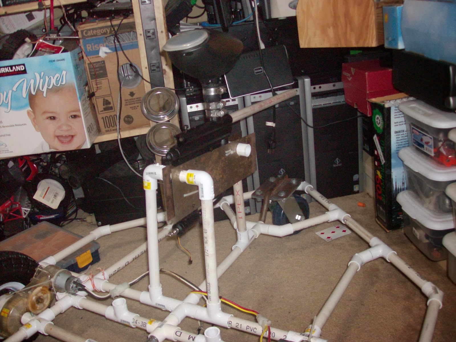
And finally, a couple of pics of the gun "mounted" on PK. In reality the gun will be closer to the base of the bot, and the front part of the tripod will be hose clamped down.


I also have been working on the motor controller, but its not done, so I will save that update for another post.

Saturday, 15 February 2014

A fairly quick PKP

Since I have been back to school, I have not had much time to work on PK, but here is a quick update:
This is a video I took of the servo actuating the trigger with an CO2 source connected to the paintball gun. The red robot on the left side was the quickest thing I could come up with to drive a servo via manual control. The reason my thumb is on the servo arm is that the servo mounting is not very strudy (really thin piece of plastic as in the last post) so the servo arm has a tendancy to slip off of the trigger. And the CO2 was low, so I had to re-cock the paintball gun after every shot. Anyway, here it is:
And as well, I found the code running on the RC controller and the motor controller, here it is, RC controller first:
#include <Servo.h>
Servo left;
Servo right;
void setup()
{
  Serial.begin(9600);
  pinMode(11, INPUT);
  pinMode(12, INPUT);
  left.attach(9);
  right.attach(10);
}

void loop()
{
  int p1 = pulseIn(11, HIGH);
  int p2 = pulseIn(12, HIGH);
  p1 = constrain(p1, 1300, 1700);
  p2 = constrain(p2, 1300, 1700);
  p1 = map(p1, 1300, 1700, 0, 180);
  p2 = map(p2, 1300, 1700, 0, 180);
 
  if (p1 < 99 && p1 > 81)
  p1 = 90;
  if (p2 < 99 && p2 > 81)
  p2 = 90;
 
  left.write(p1);
  right.write(p2);
 
  Serial.print(p1);
  Serial.print("  ");
  Serial.println(p2);
  delay(10);
}

And the motor controller:
 #define in1 11
#define pwm1 9
#define f1 5
#define b1 7
#define in2 12
#define pwm2 10
#define f2 6
#define b2 8
#define failsafe 13
void setup()
{
  pinMode(failsafe, OUTPUT);
  // Channel 1:
  pinMode(in1,INPUT);
  pinMode(pwm1,OUTPUT);
  pinMode(f1,OUTPUT);
  pinMode(b1,OUTPUT);
  // Channel 2:
  pinMode(in2,INPUT);
  pinMode(pwm2,OUTPUT);
  pinMode(f2,OUTPUT);
  pinMode(b2,OUTPUT);
  Serial.begin(9600);
}

void loop()
{
 int p1=pulseIn(in1,HIGH);
 int p2=pulseIn(in2,HIGH);
//========== Failsafe ================

 if (p1 == 0 || p2 == 0)
 {
   digitalWrite(failsafe,HIGH);
   digitalWrite(b1,LOW);
   digitalWrite(f1,LOW);
   digitalWrite(b2,LOW);
   digitalWrite(f2,LOW);
   analogWrite(pwm1,255);
   analogWrite(pwm2,255);
   delay(1);
 }
 else
 {
   digitalWrite(failsafe,LOW);
//============= Channel 1 =============
 if(p1 > 1550)
 {
   int s1=map(p1, 1550, 2000, 255, 0);
   analogWrite(pwm1,s1);
   digitalWrite(b1,LOW);
   digitalWrite(f1,HIGH);
 }
 else if(p1 < 1450)
 {
  int s1=map(p1, 1450, 0, 255, 0);
  analogWrite(pwm1,s1);
  digitalWrite(f1,LOW);
  digitalWrite(b1,HIGH);
 }
 else
 {
  analogWrite(pwm1,255);
  digitalWrite(b1,LOW);
  digitalWrite(f1,LOW);
 }
//============ Channel 2 ==============
 if(p2 > 1550)
 {
   int s2=map(p2, 1550, 2000, 255, 0);
   analogWrite(pwm2,s2);
   digitalWrite(b2,LOW);
   digitalWrite(f2,HIGH);
 }
 else if(p2 < 1450)
 {
  int s2=map(p2, 1450, 0, 255, 0);
  analogWrite(pwm2,s2);
  digitalWrite(f2,LOW);
  digitalWrite(b2,HIGH);
 }
 else
 {
  analogWrite(pwm2,255);
  digitalWrite(b2,LOW);
  digitalWrite(f2,LOW);
 }
//====================================
 }
}

And as well, I purchased rather cheaply another CO2 tank for my paintball gun (it is designed for use in a home soda maker, but it uses the same connector and holds the same amount of CO2 as a regular paintball tank)
 And this, candy despenser, I think? anyway, a nice source of acrlyic that will probably end up incorperated into PK somewhere:
And lastly, I purchased some PIR detectors for use in the targeting system, and found out that they sense motion, and pretty much ignore life for 3 seconds after that, which means I am going to have fun turning them into a tracking system, and might not be able to use them at all, but we will see. In addition, I purchased a few Arduino pro mini clones, and one will probably end up replacing the Micro Magician as the motor contoller brain, and an Arduino Mega 2560 for the main brains of PK. And that is the progress so far.

Thursday, 2 January 2014

PKP (automating a paintball gun)

On the more physical side of development on PK, I worked on how I was going to mount my Spyder Victor to PK, and how to trigger it from a microcontroller. Here is a rough mockup of what my mount will probably look like:
The grips on the gun will be unscrewed, and it will be sandwiched between 2 metal plates like so:
Behind the grip both plates will have a hole big enough for a piece of 1/2" PVC to fit thru, and that will be connected to 2 elbows which will in turn be connected to the base of the bot. In front of the air line, another hole will be cut into both plates which is big enough to fit a 1/2" tee, the tee will have pipe coming down out of it, and will be connected to another tee facing up and mounted on the center strut of PK. This will create a tripod that should hold the gun securely. On the topic of triggering it remotely, I think I have decided to use a servo mounted thru a hole in one of those plates with the servo arm resting on the trigger like so:

The servo has enough torque (barely) to pull the trigger when it is cocked, so that should work fine. On the off chance it doesn't, I have stronger (but slower) servos that could be mounted in it's place.

In this picture you can see how the metal plates will be mounted to the gun:
Of course it will be extended further than the plastic is right now, and it will be secured to the front with a pipe clamp instead of a zip tie, but that is how it should turn out. Notice the gun will be completely removable, and will remain unmodified so I can still use it when my robot isn't.

A picture of the entire gun: (yes, my barrel is 1/2" PVC, cheaper than a real barrel, and more accurite than the stock barrel)
Anyway, that's the progress so far.

Tuesday, 10 December 2013

Progress on Project Killzone

I have decided to call my large outdoor robot using the power wheels motors Project Killzone, because it will be my first weaponized robot (first with a paintball gun, and perhaps later with a small potato cannon). A couple of weeks back, I purchased some 10" I think pneumatic wheels and tires, with bearings set into them, as well as a 5" castor for the back (or possibly front, I still have not decided if I am going to make it a taildragger, or have a nose wheel) with the intention of fabricating an adapter plate that would bolt onto the 4 bolts holding the hub of the wheel together, and have the 6 (later changed to just 4, due to spacing issues) bolts sticking up to fit into the depressions of the drive motors. I have acecss to a CNC plasma cutter, so I decided to use it to fab the adapter plate. I designed the plate, and after a few false starts (see the pictures) I had 2 nice adapter plates:


The wheels also have a slightly larger ID than the power wheels axle, so some bushings were made to correct that. Here is a pic of all the things that were fabbed this weekend:

These are some photos of an adapter plate bolted onto the wheel:


And here is the whole bot as it sits, the metal tee in the middle of the axle is where the tail (or nose) wheel assembly is going to go, the tee is 1/2", as is the pipe nipple. The pipe nipple has been reamed out to a nice ID, where a metal rod fits in nicely, the metal rod goes out, and has a dogleg bent into it, in order to make the end where the castor will mount (the castor's mounting plate is a little higher than the main axle) higher. I shall weld the end of the rod that the castor is to be mounted to to a metal plate with the same dimentions as the mounting plate on the castor, and holes drilled into it for the castor to mount on. The PVC fittings are for the rest of the frame, the +s to make the outer frame and the tees will go straight up for mounting a paintball gun, compass sensor, GPS antenna, etc. on. I still plan to use the stainless dishwasher cover as a baseplate to bolt on after the frame is made.


Wednesday, 20 March 2013

Cheapness and paintball

I have a Spyder Victor paintball marker, and it is not a bad gun really, it was pretty cheap, and it gets me out on the field. I love my spyder, but I used to wish I had a longer barrel, the stock one was just not cutting it. I am a bit poor right now, and I balked at the ~$40 price tag of a nice barrel. Having just built a paintball cannon for my friend, I knew that 1/2" class 200 (thin walled) pipe fit .68 cal paintballs just fine, I also have acess to a lathe, so I figured, what the heck, I will give it a try. I measured my stock barrel's diamiter, and the legnth of the part that screws into the gun, chucked up some pipe in the lathe, and here is what I got:
admittedly, the white plastic looks a bit cheesy, but I can paint it later if I really feel like it, and the price is right ( you can get 20' of pipe (yes feet not inches) from any self-respecting hardware store for less than $5) the barrel might be a little long, but I can always cut it down later if I need to. I fired a few test shots, and it seems to work fine, no chopping, and better accuaricy.
You might have also noticed that in the pic I have a 48cu.in. HPA tank screwed onto my gun. Also in the persuit of money-saving, I purchased it and the fill station you can also see in the pic, tank was ~$40 and the fill station was ~$20 from amazon.com and ebay respectively. The fill station screws onto a scuba tank, and lets you fill your paintball tank anywhere you can lug a scuba tank. I borrowed a scuba tank from a friend, and since I can get it filled for free, I will have paid for my purchases in 6 fills, not bad considering I plan to go more than 6 times in the future, and my a few of my friends who do not want to shell out for all the new stuff said they would buy HPA tanks and buy fills from me for ~$2-$3. Doing more with less FTW!